Problem Statement:
Solution:
Conclusion:
Reference:
Radio_Shack_-_Engineer’s_Mini-Notebook_-_Basic_Semiconductor_Circuits.pdf
https://www.zpag.net/Electroniques/Kit/Radio_Shack_-_Engineer%27s_Mini-Notebook_-_Formulas_Tables_Basic_Circuits_.pdf
May 05 2020
Radio_Shack_-_Engineer’s_Mini-Notebook_-_Basic_Semiconductor_Circuits.pdf
https://www.zpag.net/Electroniques/Kit/Radio_Shack_-_Engineer%27s_Mini-Notebook_-_Formulas_Tables_Basic_Circuits_.pdf
May 05 2020
Need to understand how to use operational amplifier (Op-Amp).
Document some of the things I’ve read, watched, have been taught.
Details
The Op-Amp is a high performance linear amplifier with an amazing variety of uses. The Op-Amp has two inputs, inverting (-) and non-inverting (+), and one output. The polarity of a signal applied to the inverting input is reversed at the output. A signal applied to the non-inverting input retains its polarity at the output.
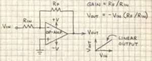
Calculation
The gain (degree of amplification) of an Op-Amp is determined by the feedback resistor that feeds some of the amplified signal from the output to the inverting input. This reduces the amplitude of the output signal, hence the gain. The smaller the resistor, the lower the gain.
Powering Op-Amps
Leads from the supply to the op-amp should be short and direct. If exceed about 6 inches, the op-amp’s supply pins must be bypasses by connecting a 0.1uF capacitor. If not, the op-amp may oscillate or fail to operate properly. If dual supply, both (pos/neg) must be the same voltage.

Warning
Never apply an input signal when the power supply is not connected.
Note
The unused inputs are grounded on multi Op-Amp chips. Is will force the op-amp to the difference between the input (Vin) and ground (0 volts). The op-amp is then a differential amplifier.
For very high input impedance and low operation current, use CMOS op-amps. Use a high-impedance voltmeter to monitor the output of an op-amp that is amplifying a D.c. voltage.
Basic Comparator
A comparator is an analog circuit that monitors two input voltages. One voltage is called the reference voltage (VRef) and the other is called the input voltage (Vin). When Vin rises above or falls below Vref, the output of the comparator changes state. Some circuits (like the 339) are designed specifically as comparators. Due to its very high open-loop gain, an op-amp with =out feedback resistor can function as a comparator.
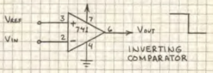
when Vin(-) exceeds Vref(+), output switches from low to high.

when Vin(+) exceeds Vref(-), output switches from high to low.
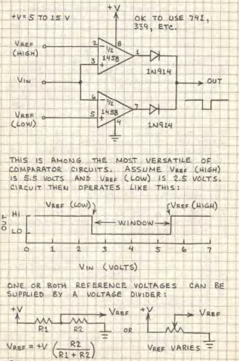
Window Comparer
Basic inverting amplifier
Input is inverted at output.
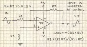
Gain = – (R2/R1)
If R1 = 1,000 ohms and R2 = 10,000 ohms, then the gain is -(10,000/1,000) or -10.
R3 = (R1/R2)/(R1+R2) [not required]
Utility-Gain inverter
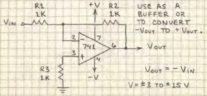
Vout = – Vin
Non-inverting Amplifier
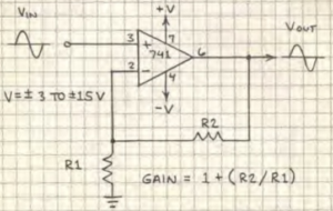
Gain = 1 + (R2 / R1)
If R1 = 1,000 ohms and R2 = 10,000 ohms, then gain is 1 + ( 10,000 / 1,000) or 11.
Unity-gain Follower
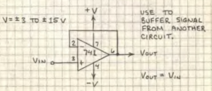
Vout = Vin
Summing Amplifier
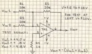
The output of the summing amplifier is the sum of the input voltages. The sum of the inputs should not exceed +-V less a olt or two. Add as many inputs as you wish. (Use 10k resistor to pin 2 for each input.)
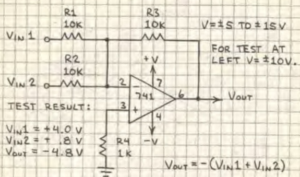
This circuit preserves the polarity of Vin.
Difference (differential) Amplifier
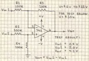
The output of the difference amplifier is Vin2 – Vin1. The input voltages should not exceed +-V.
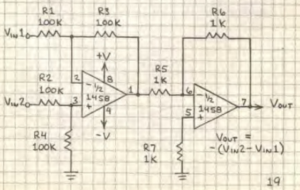
The circuit reverses the polarity of Vin2 – Vin1.
https://en.wikipedia.org/wiki/Operational_amplifier
http://www.ibiblio.org/kuphaldt/electricCircuits/Semi/SEMI.pdf (Chapter 8)
8.12. POSITIVE FEEDBACK
https://www.androiderode.com/op-amp-adder-and-subtractor-circuits/
May 05 2020
Need to understand the surface mount chip size to understand what I can solder
Find some reference data

I should stick with 1206 mm and bigger
https://en.wikipedia.org/wiki/Surface-mount_technology